


 sales@sunriver-electric.com

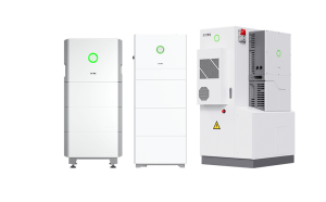
A successful installation of a sophisticated system like the SAJ HS3 begins long before the first tool is picked up. This guide is designed to be a comprehensive walkthrough of the entire process, grounded in both official specifications and real-world experience from the field.
Our goal is to provide a clear, logical roadmap for both professional installers seeking a reliable workflow and for technically-savvy homeowners who want to deeply understand the process.
Experience shows that proper preparation is the single most important factor in a smooth, safe, and successful installation.
The Pre-Flight Checklist: Preparing for a Successful Installation
Before we touch any hardware, we need to prepare the workspace, the tools, and our safety mindset. This phase ensures that once the installation begins, it can proceed smoothly and without interruption.
Required Tools & Personnel
A successful installation depends on having the right tools on hand. Here is a comprehensive checklist:

- Power & Hand Tools:
- Calibrated Torque Wrench (with sockets)
- Digital Multimeter (Cat III or higher)
- Wire strippers & crimpers
- Stud Finder
- Bubble Level
- Socket wrench set
- Drill and appropriate bits
- Personal Protective Equipment (PPE):
- High-quality, Class 0 Insulated Gloves
- Safety Glasses
- Personnel:
- This is a non-negotiable two-person job for lifting. The main inverter unit weighs 27.5 kg (61 lbs), but the individual battery modules weigh a dense 53 kg (117 lbs) each.
Time & Difficulty
| Aspect | Estimate | Remarques |
|---|---|---|
| Estimated Time | 3-5 hours | For a prepared site with no complications. |
| Difficulty | Difficult | Requires certified electrical knowledge. |
⚠️ WARNING: CRITICAL SAFETY OVERVIEW
This installation involves lethal high-voltage DC and AC electricity. Risk of electric shock, arc flash, and fire is significant if done improperly. This guide is for informational purposes only. All electrical work must be performed by a qualified and licensed electrician in accordance with all local codes and regulations. Always perform a full lockout/tagout procedure1 on the main electrical panel before beginning any wiring.
Phase 1: Site Preparation & Unboxing
Before any hardware goes on the wall, it’s critical to verify two things: that the chosen location is perfect for long-term performance and safety, and that every component has arrived safely. Taking ten minutes to do these checks can prevent hours of headaches later.
Step 1.1 – Final Site Assessment
First, you must confirm the physical and environmental suitability of the mounting location. This involves four key checks:
- Structure: Verify the mounting wall has the structural integrity to support the total weight of the system.
- Clearance: Measure and confirm you can maintain a minimum clearance of 30 cm (12 inches) on all sides and on top of the unit for proper ventilation.
- Environment: Check for environmental hazards. The location must be dry and protected from direct, prolonged sun exposure.
- Future-Proofing: A key lesson from the field is to consider the future use of the space. Avoid installing the unit in a space that you might want to use for shelves or a cabinet later, as relocating the system is a major and expensive job.

To verify this step is complete, confirm that the site is structurally sound, meets all clearance requirements, and is protected from the elements.
Step 1.2 – Unboxing & Inventory
Next, ensure you have all parts and that nothing was damaged during shipping before you begin the physical installation.
- Carefully unbox the main unit, battery modules, and any accessory boxes.
- Lay all components out on a clean, protected surface and cross-reference them with the official packing list included in the documentation.
Pro Tip: Photograph the serial numbers on the back of the unit avant you mount it. Once the unit is on the wall, these numbers are inaccessible, and you will need them for warranty registration and technical support.

This step is complete when you have confirmed all parts are present and free of any visible damage.
Important: Do not proceed if parts are missing or damaged. Contact your supplier immediately.
Phase 2: Physical Installation
This phase covers the physical mounting of the hardware. A secure, level installation is the literal foundation for a reliable, long-lasting system.
Step 2.1 – Mounting the Bracket
The bracket is the anchor for the entire system; it must be perfectly level and securely fastened to the wall structure to support a significant amount of weight.
- Use a stud finder to locate the wall studs in your chosen location.
- Hold the mounting bracket against the wall and use a bubble level to ensure it is perfectly horizontal. Mark the pilot hole locations.
- Drill pilot holes and secure the bracket to the wall using the appropriate, manufacturer-supplied hardware.

Verification for this step is simple: the bracket is level and firmly attached to the wall, with no movement.
Step 2.2 – Hanging the Main Unit & Installing Batteries
This step involves heavy lifting and the initial assembly of the core components. Following the correct sequence is critical for the system to function.
⚠️ WARNING: This is a two-person lift. The battery modules weigh 53 kg (117 lbs). Attempting to lift them alone risks injury and equipment damage.
- With a partner, carefully lift the main HS3 unit and hang it securely on the mounting bracket. Install the locking screws.
- Open the battery compartment. Install the battery modules one by one, following the exact sequence specified in the manual.
Pro Tip: If a battery module doesn’t "click" into place easily, don’t force it. Remove it and check for any obstructions in the guides or connectors. Forcing it can damage the sensitive connection pins.

This step is complete when the main unit is secure on the bracket, and all battery modules have audibly clicked into place.
Important: Recent Discussion shows that installing battery modules in the wrong sequence is a common cause for "Battery Not Detected" errors during commissioning. Double-check the sequence now to save a major headache later.
Phase 3: Electrical & Data Connections
This is the most critical and dangerous phase of the installation. Precision and safety are paramount as these connections form the central nervous system of the energy storage system. From our experience, the vast majority of long-term issues can be traced back to mistakes made during this phase.
Step 3.1 – System Grounding
Proper grounding is the single most important safety feature of the entire system. It protects against electrical faults and is non-negotiable.
- Connect the HS3 chassis grounding point to the home’s main grounding electrode conductor using the appropriately sized copper wire as specified by local code.

Verify that the grounding connection2 is tight, secure, and meets all local electrical code requirements.
Step 3.2 – DC & AC Wiring
This is where we connect the power—from the solar panels into the system, and from the system into your home. Polarity and connection security are critical.
⚠️ WARNING: Confirm the main electrical panel and the solar DC disconnects are in the OFF position and locked out (lockout/tagout procedure1). Verify all circuits are de-energized with a multimeter before touching any wires.
- DC Connection:
- Connect the solar array strings to the PV input terminals on the HS3.
- Crucially, verify the polarity (+/-) of each string with a multimeter before plugging it in. Reversing polarity can permanently damage the inverter.

- AC Connection:
- Connect the HS3’s AC output (Grid and Backup/Load) to the dedicated circuit breakers in the main electrical panel.


Pro Tip: Always use a calibrated torque wrench on the terminal lugs. The official specification for the main terminals is 2.0 Nm. ‘Hand-tight’ is not sufficient and is a leading cause of failures.
Verify that all connections are torqued to spec and match the wiring diagram.
Step 3.3 – Installing the Current Transformers (CTs)
The CTs are the ‘senses’ of the system. If they are installed incorrectly, the system is flying blind and cannot make smart decisions about when to charge from solar or discharge to the home.
- Clamp the CTs around the main service lines coming into the house from the utility meter.
Pro Tip: Installer forums consistently report that incorrect CT orientation is the #1 cause of inaccurate app readings. The arrow on the CT sensor must point towards the public grid.
 - SAJ HS3")
Verify that the CTs are placed on the correct wires and are oriented in the right direction.
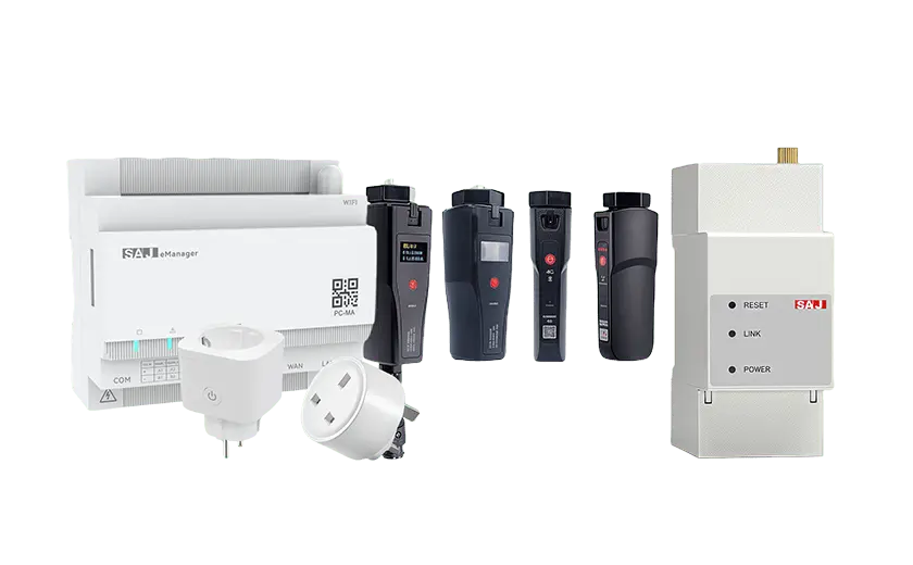
Step 3.4 – Data & Communication Wiring
This step enables the HS3 to communicate with other devices like external meters or generators, unlocking its most advanced energy management features.
- Identify the communication ports on the HS3 (e.g., CAN, RS485, DRM).
- Run shielded communication cables from the HS3 to the external device(s).
- Land the wires on the correct terminals according to the device manual.
Pro Tip: Don’t bundle communication cables tightly with high-power AC/DC cables. This can cause electromagnetic interference (EMI) and lead to intermittent communication errors that are very difficult to troubleshoot later.

Verify that the communication cables are securely connected to the correct ports.
Phase 4: Commissioning & Verification
This is the exciting part: safely bringing the system to life. This phase is all about a careful, step-by-step power-up and software setup to ensure a smooth start and verify that all our work was done correctly.
Step 4.1 – The Power-Up Sequence
Powering the system on in the correct sequence is crucial to allow the internal electronics to initialize properly and prevent damage.
Follow this exact, numbered sequence:
- Turn ON the main Battery breaker.
- Turn ON the DC disconnect from the solar array.
- Turn ON the AC breaker that connects the HS3 to the main panel.

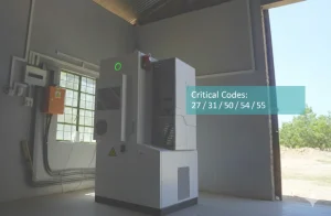
The verification for this step is seeing the status LEDs on the unit light up and indicate a successful startup with no immediate error codes.
Step 4.2 – Software & Network Configuration
This step connects your system to the cloud and your smartphone, giving you full control and visibility over your home’s energy.
- Use the onboard display or app to connect the HS3 to the local network via Wi-Fi or Ethernet.
- Download the eSAJ app to your smartphone, create an account, and add your new system by scanning its QR code.
Important: Before configuring any settings, perform a firmware update. Real-world user feedback shows this single step can prevent numerous initial setup errors, including the common "Battery Not Detected" fault.
- In the app, navigate to the settings and configure the primary operating mode. Common options include:
- Self-consumption: Prioritizes using solar/battery power for the home.
- Time-of-Use: Optimizes charging/discharging to save money on TOU rates.
- Full Backup: Keeps the battery at a high state of charge for grid outages.

This step is complete when the HS3 system is online and visible in the eSAJ app on your phone, and you can see real-time data.
Post-Commissioning & Next Steps
The installation is done, but the job isn’t finished. This section ensures you’re confident that the system is running perfectly and you know what to do next to get the most out of your investment.
Final Verification Checklist
| Check | Expected Result |
|---|---|
| PV Power Flow | In the app, power flow from the PV array should be visible. |
| Battery Status | The app should show the battery’s correct state of charge (SoC). |
| Grid Readings | The app should show accurate grid import/export values. |
Troubleshooting the Top 3 Initial Problems
- "Battery Not Detected":
- Likely Causes: Firmware out of date, incorrect battery installation sequence, loose communication cable.
- Solution: Perform firmware update, re-check installation sequence, inspect cables.
- "App Readings are Incorrect":
- Likely Cause: This is almost always a CT installation issue.
- Solution: Verify CTs are on the correct service lines and the orientation arrow points to the grid.
- "Wi-Fi or Network Connection Issues":
- Likely Causes: Router is too far, incorrect password.
- Solution: Check router distance, re-enter Wi-Fi credentials.
Warranty & Support
- Explain the process for registering the product warranty online.
- Provide clear links to the official user manual download page and technical support contacts.
Final Word: Core Principles for a Safe and Reliable System
After guiding many through this process, we’ve distilled the keys to success down to three core principles.
Principle 1: Meticulous Preparation is Key. A successful installation is determined before a single tool is used. A thorough site assessment, a complete inventory of parts, and a clear understanding of the process are non-negotiable.
Principle 2: Precision Protects Performance. From torquing terminals to orienting CTs and following the correct power-up sequence, every step matters. Precision is the difference between a system that works and a system that works optimally for years to come.
Principle 3: Safety is Non-Negotiable. This system involves lethal voltages. There is no substitute for qualified professionals, proper safety equipment, and a methodical, safety-first mindset.
A properly installed system is a reliable and valuable asset for years to come.